
VIO GNSS calibration
Summary #
GNSS and Visual Inertial Odometry (VIO) calibration is an important step for fusion. GNSS positions are globally referenced and always aligned to the North, while VIO reference and orientation depend on the camera’s starting point. Combining this data requires finding the world transformation that allows the projection of the VIO reference frame into the GNSS reference frame, and vice versa.
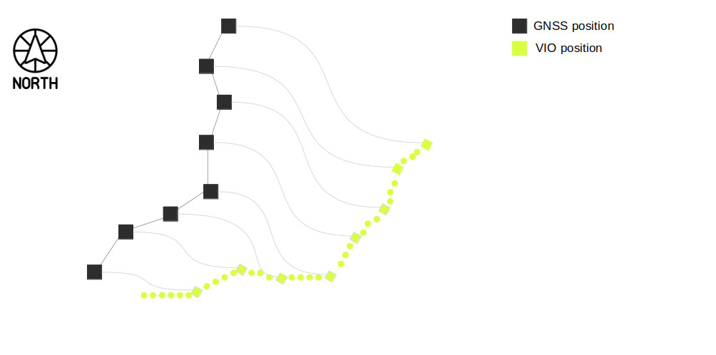
The differences between the VIO and GNSS trajectories of the same moving agent are illustrated in the following figure. It is important to note that these trajectories have different origins, highlighting the need for alignment between the VIO and GNSS systems. Please also note that synchronized GNSS / VIO data pairs are linked by a thin gray line.
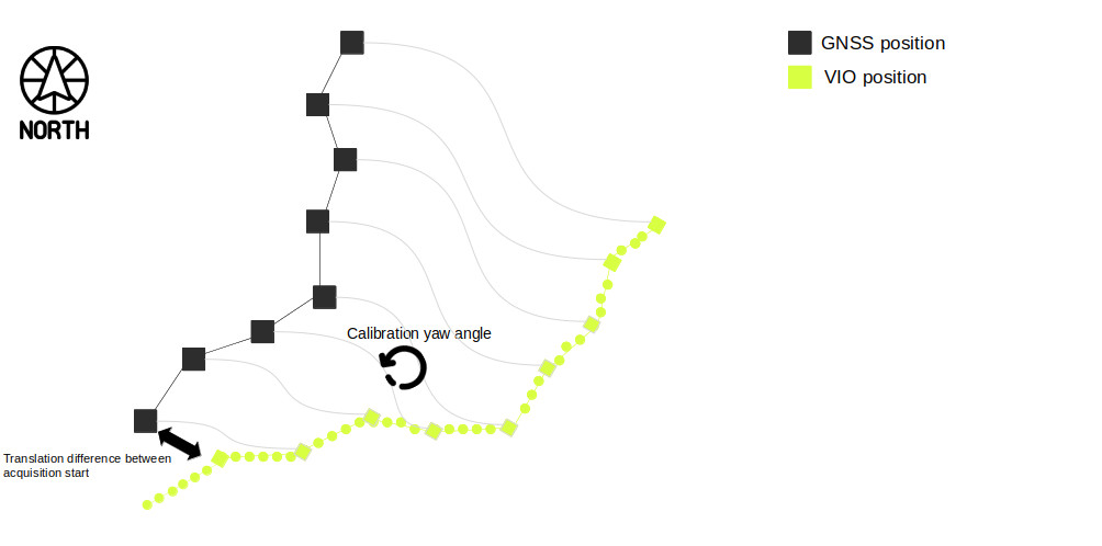
The VIO path sent for fusion is consistently aligned with gravity. As illustrated in the following figure, aligning the VIO and GNSS systems requires determining 4 parameters:
- The yaw rotation (1 parameter) between the GNSS coordinate system and the VIO coordinate system.
- The translation (3 parameters: X-Y-Z) difference between the start of VIO acquisition and the start of GNSS acquisition.
Coordinate system model #
In all our schematics, the transformations are expressed in a coordinate basis mean. Let’s explain this. Let’s suppose that you have two coordinate systems A and B. Each coordinate system could be related to each other thanks to another coordinate system named W following the schematics below:
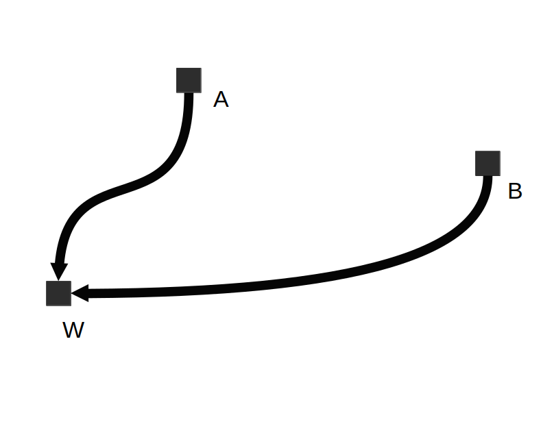
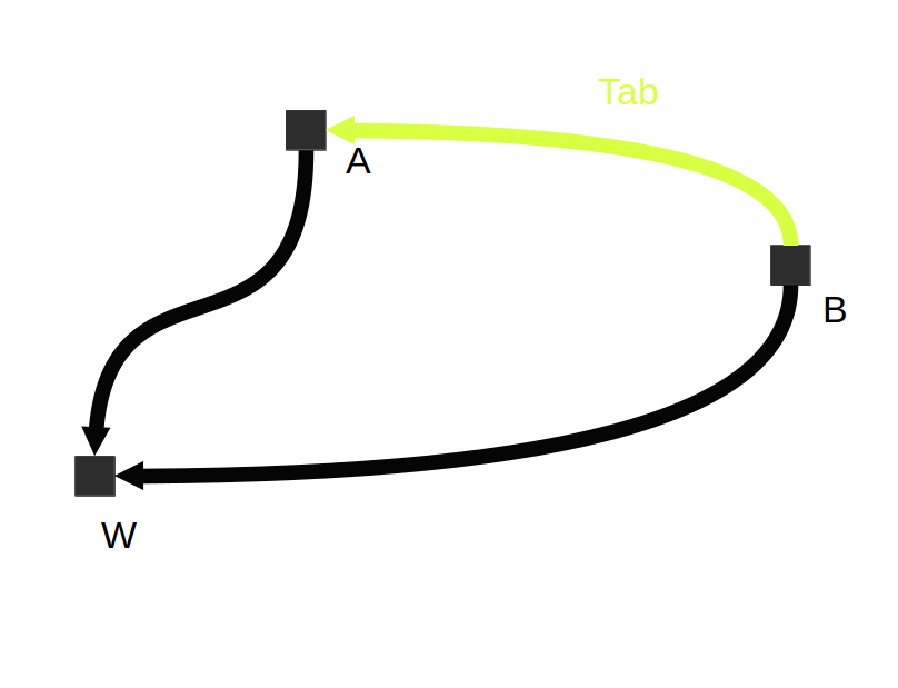
The transformation matrix that allows a coordinate system change between B and A could be defined as Tab = inverse(A) x B:
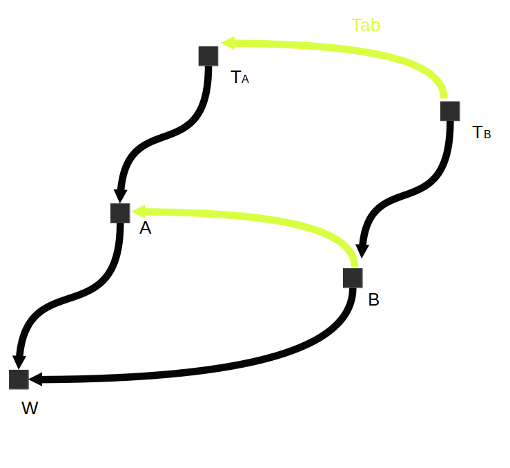
Let’s now consider a transformation expressed in coordinate system A, noted Ta, and the same transformation expressed in coordinate system B, noted Tb, following the schematics below. The link between these transformations could be noted as:
Tb = inverse(Tab) x Ta x Tab
and
Ta = Tab x Tb x inverse(Tab)
Following our definitions above, we could define the VIO and GNSS coordinate systems and establish the link between them. This is expressed in the schematics below. The Tcalib transformation is what is estimated by GNSS / VIO calibration. It could be retrieved thanks to getGeoTrackingCalibration method.
On the other hand, the Tantenna transformation is provided thanks to the gnss_antenna_position parameter. If it is not specified, it will be set to identity.
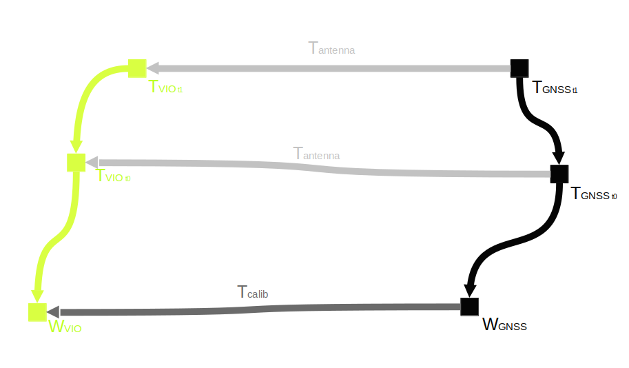
T_VIO_projected_in_GNSS = T_calib x T_VIO x T_antennaT_GNSS_projected_in_VIO = inverse(T_calib) x T_GNSS x inverse(T_antenna)
These formula are helpful for understanding what it is done under the hood.
However, in practice please use Camera2Geo and Geo2Camera functions that project VIO or GNSS into the requested coordinate system.
GNSS / VIO calibration stop criteria #
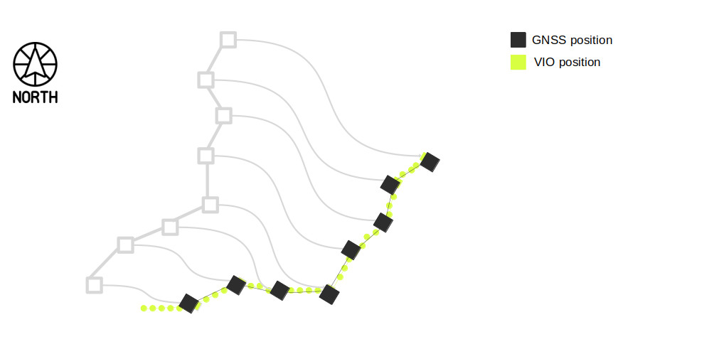
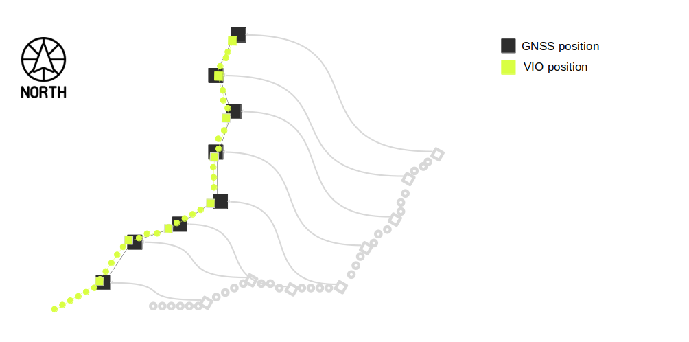
The GNSS/VIO calibration process halts based on calibration uncertainty according to stopping criteria. Put simply, calibration concludes when a significant level of confidence in the T_calib transformation is obtained. The following figure shows this principle in 2D.
Set target calibration uncertainty with the API #
The API provides the ability to specify the target calibration uncertainty. Here are the main attributes:
- Target yaw uncertainty: You can set the target yaw uncertainty by using the target_yaw_uncertainty attribute.
- Target translation uncertainty: You can set the target translation uncertainty by using the target_translation_uncertainty attribute.
📌 Note: by default, only the yaw uncertainty is taken as the final calibration criterion. If you want to include translation, you need to set the enable_translation_uncertainty_target parameter to
true.
My application needs quick estimation of the GNSS / VIO calibration #
If your use-case requires a quick estimation of the current GeoPose, you can enable the option enable_rolling_calibration. This allows the system to utilize the initial calibration estimation for computing GeoPose, even if the accuracy of these initial estimations may not be optimal yet.
Set calibration parameters inside SDK #
As introduced previously the calibration parameters can be set using the GNSSCalibrationParameters object. Here is a full example
sl::PositionalTrackingFusionParameters positional_tracking_fusion_parameters;
sl::GNSSCalibrationParameters gnss_calibration_parameter;
gnss_calibration_parameter.enable_reinitialization = false;
gnss_calibration_parameter.enable_translation_uncertainty_target = false;
gnss_calibration_parameter.gnss_vio_reinit_threshold = 5;
gnss_calibration_parameter.target_yaw_uncertainty = 1e-2;
gnss_calibration_parameter.gnss_antenna_position = sl::float3(0, 0, 0); // Please set your Antenna position here
positional_tracking_fusion_parameters.gnss_calibration_parameters = gnss_calibration_parameter;
positional_tracking_fusion_parameters.enable_GNSS_fusion = true;
sl::FUSION_ERROR_CODE tracking_error_code = fusion.enablePositionalTracking(positional_tracking_fusion_parameters);